Translate page

Wednesday, April 23, 2025

Pranjal Joshi – From Code to Chips: How a CSE Girl Found Her Place in the VLSI Industry

Pranjal Joshi’s story is not the typical “CSE-to-software-success” arc. After completing her Computer Science Engineering degree, she joined a reputed software company—something most of her peers celebrated. But for Pranjal, the spark just wasn’t there.

Day after day of routine coding left her feeling disconnected. It wasn’t the kind of impact she had envisioned making. “Is this really what I want to do for the rest of my life?” she often asked herself.

A New Direction: The VLSI Trigger

During this phase of uncertainty, a college senior who had transitioned into the semiconductor industry introduced her to VLSI EXPERT. Curious and hopeful, Pranjal reached out and eventually connected with Puneet Mittal, the founder of VLSI EXPERT.

Their conversation changed everything.

Pranjal recalls, “That one interaction gave me more clarity and confidence than I had felt in months. Puneet sir didn’t just talk about the industry—he showed me a path I never knew existed.”

Encouraged and inspired, she enrolled in the Placement-Oriented Program offered by VLSI EXPERT, under the direct mentorship of Puneet Mittal and Niti Gupta.

Training That Changed Her Trajectory

The program was intense. It covered everything—from Digital Design and Verilog to RTL to GDSII flow, timing constraints, and tool-based hands-on training. For someone from a CSE background, these were new and challenging territories. But Pranjal approached every concept with unwavering dedication.

What stood out was not just the technical depth, but the ecosystem of support:

  • Assignments that tested her understanding

  • Mock interviews that prepared her for the real-world

  • Continual feedback that refined her learning journey

She says, “The way Puneet sir and Niti ma’am explained each topic—it wasn’t just teaching, it was mentoring. I never felt like I was doing this alone.”

Her Breakthrough

Within a few months, Pranjal built a strong portfolio of projects. She became comfortable talking about setup/hold violations, floorplanning, clock tree synthesis, and even scripting for automation in the flow—something her software roots helped with.

Her confidence showed in interviews. When asked about her transition, she proudly shared, “It’s not easy, but it’s not impossible either—especially when you have the right mentors.”

She cracked her placement in a semiconductor company’s Physical Design team, leaving the interviewers impressed with her clarity, practical knowledge, and composure.

Where She Is Now

Today, Pranjal is a Physical Design Engineer, working on real-world chips that power smart devices. From CSE classrooms to chip tape-outs—her journey is a reminder that it’s never too late to pivot with purpose.

Key Takeaways for Students:

  • Don’t ignore dissatisfaction—sometimes it’s the push you need toward something greater.

  • Right guidance can make a world of difference. Mentors matter.

  • With dedication and structured learning (like the Placement Oriented Program by VLSI EXPERT), even non-ECE students can thrive in VLSI.

  • The mock interviews, hands-on assignments, and constant support prepare you for not just a job but a career.

In her words - let's hear her voice.


Wednesday, October 23, 2024

Advance SDC Techniques for Efficient Timing Closure - Part 1

Introduction to Advanced SDC Techniques

SDC is an industry-standard format used to specify the timing, design, and operational constraints for ASIC and FPGA designs. It’s crucial for various EDA tools like synthesis, static timing analysis (STA), and place-and-route.

Note:- Basic Of SDC (Our Previous Blog)

Key Concepts:
  • Clock Definition: Specifies the clock waveforms and timing characteristics.
  • Input/Output Delays: Defines constraints for signal arrival and output times.
  • Timing Exceptions: Includes paths that need special treatment (e.g., false paths, multi-cycle paths).
  • Design Rules: Set up max fanout, transition times, and other physical rules.
Usage in Physical Design SDC files guides the timing closure process by helping tools optimize the layout and logic to meet the defined timing requirements. Accurate SDC constraints ensure designs meet performance specs and are manufacturable. 
This is all we have covered in the previous articles. Now, it's time to dive into advanced techniques for handling more complex designs and optimizing timing closure. There may be a few places, where you might be thinking that it's advanced and you ned more clarity of topics, in that case, drop me an email or comment - I will try to add those on priority

1. Multi-Mode Multi-Corner (MMMC) Constraints 

In real-world designs, chips operate in various modes (e.g., functional mode, test mode, high-performance mode and low-power modes etc) and under different conditions (process, voltage, temperature). SDC must account for these variables simultaneously, which is managed through MMMC constraints. We have to make sure that the design meets timing in all such modes. 
Tools like Synopsys PrimeTime allow for multiple scenarios to be loaded, helping analyze the timing across different modes and corners. 

Attention:- If you are not aware of "Functional and Test Mode" and what are these "different conditions - process, voltage, and temperature" - Wait for some time, and I will explain it to you in another article. 

Command Pointer (for Synopsys tools):- set_operating_conditions and set_mode commands can be used to switch between these modes. 

Note:- Detailing for this topic is in next article

2. Clock Grouping and Complex Clock Relationships 

Many designs have multiple clocks running at different frequencies or phases, which makes timing analysis complex. And as we know that clock is very crucial part of the design and register to register timing analysis depends on clock definition itself. Now, assume that one set of data is travelling from 1 flipflop (triggered by 1 clock) and captured by other flipflop (triggered by other clock), then how will you do the timing analysis between them. If need to handle the constraint between them properly.
Similary, when clocks are asynchronous, you can specify them as "logically exclusive," meaning no paths are analyzed between them, thus simplifying timing. 

SDC provides commands like set_clock_groups to define relationships between clocks. In multi-clock systems like SoCs, the set_false_path command can be used for paths between clocks that don't need timing analysis. Defining proper clock domains with create_clock and grouping them helps avoid unnecessary timing violations. 

Attention:- If you are not aware of "clock domain", "asynchronous clocks", "register to register timing analysis", "basic clock constraints" - read my previous articles or wait for upcoming articles.

Command Pointer:- set_clock_groups, set_false_path

Note:- Detailing for this topic is in next article

3. Handling Advanced Timing Exceptions 

Designers often apply multi-cycle paths or min/max delay constraints when some paths can take more than one clock cycle to complete. These exceptions help optimize timing and reduce pessimism in the analysis. as per your circuit requirement, a path between two low-speed components may have relaxed timing because data does not need to be transferred every clock cycle. In such scenario,  using set_multicycle_path, we specify how many cycles a path can take, and set_min_delay or set_max_delay helps control specific delays between launch and capture registers. 

Pointer:  May be you thinking what's the big deal if it's taking more than1 cycle and you are right but problem is how tool will come to know that it's taking more than 1 cycle. We as a designer have to inform the tool that it will take more than 1 cycle to give me correct data. Remember - correct data is important at this point because capture flipflop will receive some data at the end of the 1 cycle but as a timing analysis tool, it don't know what is correct and wrong data. For the tool it's a data but Designer only know what's correct and wrong. So, designer has to inform the tool when the correct data will reach - after 1 cycle or 2 cycle or more then that. And this information we provide as part of Timing Exception using Multicycle path. We will discuss more about this in other article.

Attention:- If you are not aware of "Multi-cycle paths", "min/max delay constraints" or "Timing Exceptions" - read my previous articles or wait for upcoming articles.

Command Pointer:- set_multicycle_path, set_min_delay, set_max_delay

Note:- Detailing for this topic is in next articles

4. Power-Aware SDC for Low-Power 

Designs Low-power constraints are essential in designs where energy efficiency is a priority. Power-aware SDC integrates power domains with timing constraints. You can define power gating, multi-voltage islands, and clock gating effects through SDC to define how signals interact between different power domains. 
Tools like Synopsys PrimeTime PX use these constraints to perform power-aware timing analysis. 

Attention:- If you are not aware of "Low Power", "power gating" or "Multivoltage islands", "clock gating" - read my previous articles or wait for upcoming articles.

Command Pointer:- set_isolation, set_level_shifter, set_power_domain

Note:- Detailing for this topic is in next articles

5. Automating SDC Generation and Validation 

Managing SDC for complex designs requires automation to reduce errors. Custom scripts can help generate SDC files for different blocks or modes automatically. Automation scripts can extract timing requirements from RTL or netlists and generate appropriate SDC constraints, saving time during design iterations.
Tools like Synopsys Design Compiler provide utilities to validate and automate SDC generation, ensuring that constraints are consistent and correct throughout the design flow. 

Note:- Detailing for this topic is in next articles


This article is setting a base for future articles related to SDC (Synopsys Design Constraints). We will discuss in upcoming articles the advanced part of SDC from the SOC point of view.

Stay Tune.

Wednesday, March 20, 2024

Semiconductor Physics: Electron Spinning in an ATOM

Electron Spinning in an ATOM

We have discussed in our previous article (Semiconductor Physics:- Electron Configuration In Atom, about the atoms (and analogy) and the basic idea of electron movement. If you remember, we have finished our article just introducing the spining of electrons in 3D dimensions and about the quantum numbers

  • n - principal quantum number – This is same number as we know orbital no. 

  • l - azimuthal quantum number – This is same as we know s,p,d,f 

  • m - magnetic quantum number.

"Among the three quantum numbers, there is another quantization condition called spin (s) that electrons should fulfill. Every electron has its angular momentum or spin and can be expressed as..."

Before going through the periodic table, there is the Pauli exclusion principle which stated that no two electrons have the same quantum numbers (n, l, m, and s). In other words, two electrons may have the same quantum number n, l, and m states but the spin states must be +1/2 and -1/2.

The configuration of electrons in different energy states is summarized in Table 1.


Table 1 The allowed energy states and the occupation of maximum number of electrons according to quantum rules.


       As an example, for the 3rd electronic orbit (n=3), l should be 0, 1, and 2 followed by equation 14. Similarly, m should be -l to +l including zero for each l value. Electrons can occupy each m value with a spin +/-1/2.

The different notations for different l values are used to express the electronic configuration 

l = 0,1,2,3,4,5 .......

l = s, p, d, f, g, h, .....

The electron state can be represented as


I think now you are able to understand whole electron configuration which you have studied in your college days. Let’s talk about few more examples, so that you can be familiar with Semiconductor and Physics very well.


For example, Si (Atomic No=14) and Ge (Atomic No= 32), the electronic configuration is

Si         1s22s22p63s23p2

Figure 5 Electronic configuration of Silicon


Ge         1s22s22p63s23p64s23d104p2

Figure 6 Electronic configuration of germanium


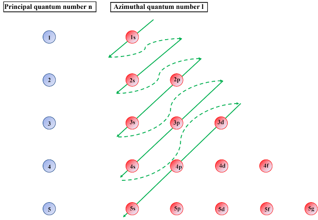
The electronic arrangements are shown in figure1


Electronic Configuation

Figure 7 Electron’s configuration rule

In the next article, we will discuss the different type of bonding between the ATOMS and the formation of energy bands which will help us to understand the Semiconductor Physics more deeply and later semiconductor Devices like PN Diode, MOSFETs and all.


By - 

First Author - Dr. Bhaskar Patnayak

Second Author (Editor) - Mr. Puneet Mittal 

Saturday, March 16, 2024

Semiconductor Physics:- Electrons configuration in Atom

Electrons configuration in Atom as per Quantum Mechanics

 To understand the movement of electrons in a semiconductor device, we need to understand the electronic configuration of an atom and how it interacts with the crystal lattice. We already know that atom consists of Neutrons (neutral charge) and Protons (positive charge) inside a nucleus &  Electrons (negative charge) revolved around the nucleus (Figure 1).

Figure 1 Atomic structure


Note: (Just for your information) If you remember in the intermediate level or BTech 1st year, we have studied in quantum mechanics that these electrons are restricted to certain energy levels (quantized). In this regard, Plank’s blackbody radiation and Einstein’s photoelectric effect established the discrete nature of light (quantization). In the late 1920s, quantum mechanics had developed in which Heisenberg developed matrix mechanics and Schrödinger developed wave mechanics at the same time. Although the mathematical formulations are quite different, the basic principles are identical.

Although The Schrödinger equation describes the interaction between particles (e.g. electrons) and potential field, it’s enormously difficult to solve the Schrödinger equation in the case of complicated atoms (Atomic number greater than 1 or you can say the total no. of electrons in a neutral atom). Therefore, the solution of the hydrogen atom (atomic number 1) is significant to understand the permissible energy states for electron arrangements.

It is well known that a hydrogen atom consists of a single electron and a proton system. We can call this system a two-particle system. In some circumstances, the two-particle system's motion can be described as the motion of a single particle with respect to a center of mass. The mass of the particle is referred to as a reduced mass with respect to the center of the mass system. In this consideration, we’ll assume that the electron is relatively moved around the proton, and the proton is located at the center (in this case at the origin). Since protons have higher mass with respect to the electron, therefore we will consider the reduced mass is equal to the electron mass, and the proton is located at the origin.


Figure 2 (a) Center of mass concept. (b) Position of an electron with respect to proton (Origin)

 Note: - I know you may be thinking what is this. Why are we assuming so many things and nothing is fixed? Basially, in an atom when we say that Proton is in center, then its important to understand which center are we talking about! 

Let me explain you in my (Puneet's way) and you try to visualise it. (People or scientist may not like it but at least you can understand it. From analogy point of view you can consider it's a cloud system. When we see a cloud can we say that it's a 1 cloud of this size, this is the boundry and this is center of cloud. but still we see that whole piece of cloud moving together and merging with other piece of cloud and they have center also and outer periphery also. So this ATOM structure is like that. Now, Try to understand.

  • A Cloud system having more denser at the center (which is also moving) or say that become center of whole cloud (center of the mass system).
  • This cloud portion which is present in the center we are saying it's Proton.
  • Rest of the portion of cloud, you can say it's electron. (remember this I am trying to explain you for Hydrogen atom)
  • Now, you can say that if these are 2 things, can we separate out but that's not going to happen or I say if it will separate out then whole system collapse, so I (scientist) said that both are related to each other (one as positive and other as negative). if you seperate out these 2, whole cloud system collapse. So, when these 2 are together then we say it's an ATOM.
  • But still outer part of Cloud can be separate out from Center part and someother part can come and replace it. So, with respect to center part, outer part (electron) is tied with center part (proton).
Now, Read once again the above one and then below one. You will get more clearity.

The electrons and nucleus (especially protons) are interacted with by the Coulombic potential

Figure 3 Spherical polar co-ordinate system


Let’s try to understand a few key points/equations of Quantum mechanics. If you are interested, you can go into detail by referring to the standard textbooks. Here we are just capturing for reference purposes.

Note:- If you want to skip, go to equation no 11 directly but I will recommend to read it once.

Assume that the potential distribution is spherically symmetric, a time-independent three-dimensional Schrödinger equation in spherical coordinates can be written as


Note:- Hold ON - If you are thinking about so many equations - It's okay. All these are important (may be not today but it will be one day). I will explain you. Just read it once. 

The negative expression specifies that the electrons are bound with the nucleus and the energy is quantized. It should be noted that the value of n should not be zero as the energy expression become invalid. Therefore, n should be an integer.

Note:- Puneet's Way: - 
When Scientist studied it further they come to know the cloud is not in 2D and presence of outer area of cloud has some pattern in 3D (Dimensional). Also they figured out that outer surface have some motion and usually this motion is around the inner surface (neculus system - dense part) and this moment is not in X, Y, Z direction only but it's in angular form also. Remember - Whole Cloud system is moving but we are talking about the relative motion of outer cloud with respect to inner cloud (mass). and that's the reason of "Spherical polar co-ordinate system" come into the picture to correctly captured this whole system.

Among the three quantum numbers, there is another quantization condition called spin (s) that electrons should fulfill. Every electron has its angular momentum or spin and can be expressed as

So, you might be thinking why all this??

I will say, have patience and we will explain all this to you in coming articles. This is an intro article. This will help you to understand the moment of electrons in the other orbits (also in outer most orbit, which is very important to understand as we always talk about Valency electron and Valence Band).

By - 

First Author - Dr. Bhaskar Patnayak

Second Author (Editor) - Mr. Puneet Mittal 

Thursday, February 3, 2022

Verilog HDL - Lexical Conventions


HDLs provide ways to represent the digital circuits in the textual form. Verilog HDL is a HARDWARE DESCRIPTION LANGUAGE to model the digital circuits, this source code is written in a text file with the extension [ *.v ]. 


Any source code is created with the combination of characters and words which are called KEYWORDS and SYNTAX/SEMANTICS. These are globally called lexical tokens. Combination of more than one lexical tokens originate LEXICAL CONVENTIONS.


1.  LEXICAL CONVENTIONS

Lexical tokens in Verilog HDL are given below:

  • white space
  • comment
  • operator
  • number
  • string
  • identifier
  • keyword

1.1  white space or blank spaces

White spaces are used in the strings which can be incorporated using the double quotes (“). Follow the below table containing the semantics required to provide the white spaces in the string sequence:

Escape String

Character produced by escape string

\n

New line character

\t

Tab character

\\

\ character

\”

“ character

\ddd

A character specified in 1-3 octal digits (0 <= d <= 7)


If less than three characters are used, the following character shall not be an octal digit. 

Implementations may issue an error if the character represented is greater than \377.


1.2  comments

Comments are used to increase the readability of code. Comments are ignored by the Simulator. Verilog HDL has two forms to introduce comments in the source code which are given below:

1.2.1.  Single Line Comment

// This line is commented.

1.2.2.  Multiple-Line Comments

     /* This line is commented.

          This line is commented on too. */


1.3  operators

The operation which is to be performed is decided by operators. There are three kinds of operators available in Verilog HDL which are given below:

1.3.1.  Unary Operator: work on single operands.

1.3.2.  Binary Operator: work on two operands.

1.3.3.  Ternary Operator: work on three operands.

1.4  numbers

Constant numbers are represented in two ways:

  • Integer Constants

  • Real Constants


1.4.1  Integer Constants

Integer constants can be specified in decimal, hexadecimal, octal, or binary format.

There are two forms to express integer constants which are given below:

  • A.  Simple decimal number, which shall be specified as a sequence of digits 0 through 9, optionally starting with a plus or minus unary operator.
  • B.  Based constant, which shall be composed of up to three tokens.
    • an optional size constant, shall specify the size of the constant in terms of its exact number of bits.
    • an apostrophe character (', ASCII 0x27) followed by a base format character, shall consist of a case insensitive letter specifying the base for the number. Legal base specifications are d, D, h, H, o, O, b, or B, for the bases decimal, hexadecimal, octal, and binary respectively. The apostrophe character and the base format character shall not be separated by any white space.
    • the digits representing the value of the number.

It shall be legal to macro substitute these three tokens.

Negative Constant Numbers

Simple decimal numbers without the size and the base format shall be treated as signed integers,

whereas the numbers specified with the base format shall be treated as signed integers if the s designator is included or as unsigned integers if the base format only is used.

The s designator does not affect the bit pattern specified, only its interpretation.

A plus or minus operator preceding the size constant is a unary plus or minus operator.

e.g., -4 or +4

A plus or minus operator between the base format and the number is an illegal syntax.

-4'd7 // Used for performing unsigned integer math, will be stored as 2's complement of 7

-4'sd7 // Used for performing signed integer math

4'd-7 // Illegal

Unsized Constant Numbers

Numbers specified without a base format are considered as decimal numbers by default. Numbers that are written without size are simulator/machine specific but must be at least 32 bits.

659 // is a decimal number

'h 837FF // is a hexadecimal number

'o7460 // is an octal number

4af // is illegal (hexadecimal format requires 'h)

Sized Constant Numbers

4'b1001 // is a 4-bit binary number

'D 3 // is a 5-bit decimal number (Simulator/Machine Specific)

X or Z Values

3'b01x // is a 3-bit number with the least

// significant bit unknown

12'hx // is a 12-bit unknown number

16'hz // is a 16-bit high-impedance number

16'sd? // the same as 16'sbz

The default length of x and z is the same as the default length of an integer.

1.4.2  Real Constants

Real numbers are specified as given below:

  • decimal notation (e.g., 14.72)

  • scientific notation (e.g., 39e8)

  • scaled notation (e.g., 24.7K)

Real numbers expressed with a decimal point shall have at least one digit on each side of the decimal point.

Underscore Character

The underscore character is legal anywhere in an integer constant.

The underscore character is legal anywhere in a real constant except as the first character of the constant or the first character after the decimal point. The underscore character is ignored by the simulator.

E,g., 16’b1011_1000_1111_1010 // Underscore increase the readability of a number constant


1.5  string

A string is a sequence of characters enclosed by double quotes ( " ) and contained on a single line. Strings used as operands in expressions and assignments shall be treated as unsigned integer constants represented by a sequence of 8-bit ASCII values, with one 8-bit ASCII value representing one character.


1.6  Identifier

Identifier shall be used to give an object a unique name so it can be referenced. An identifier shall either be a simple identifier or an escaped identifier.

Simple Identifier

It shall be any sequence of letters,digits, dollar signs ($), and the underscore characters (_).

The first character of an identifier shall not be a digit or $; it can be a letter or an underscore. Identifiers shall be case sensitive.

e.g.,

    shiftreg_a

    busa_index

    error_condition

    merge_ab

    _bus3

    n$657

Implementations may set a limit on the maximum length of identifiers, but they shall be at least 1024 characters. If an identifier exceeds the implementation-specified length limit, an error shall be reported.

Escaped Identifiers

Escaped identifiers shall start with the backslash character (\) and end with white space (space, tab, newline, or formfeed).

They provide a means of including any of the printable ASCII characters in an identifier (the decimal values 33 through 126 or 21 through 7E in hexadecimal).

Neither the leading backslash character nor the terminating white space is considered to be part of the identifier. Therefore, an escaped identifier \cpu3 is treated the same as a non-escaped identifier cpu3.

e.g.,

    \busa+index

    \-clock

    \***error-condition***

    \net1/\net2

    \{a,b}

    \a*(b+c)


1.7  Keyword

Keywords are special identifiers reserved to define the language constructs. Keywords are in lowercase.

Must Read Article

Related Posts Plugin for WordPress, Blogger...